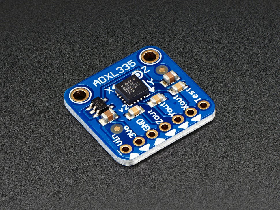
Complete Guide ADXL335 Accelerometer with Arduino Interfacing Circuit Diagram Accelerometers detect the magnitude and direction of acceleration. We can use them to measure acceleration or to turn on a device by tapping. In this video we will learn how to get the raw data
Simple Hookup This example will use an Arduino Uno to collect and interpret the sensor data from the ADXL337 or ADXL377. Since the sensors' outputs are analog, all we need are three wires between the Arduino's 'Analog In' pins and accelerometer (aside from power and ground).
6050 Accelerometer and Gyroscope Sensor Circuit Diagram
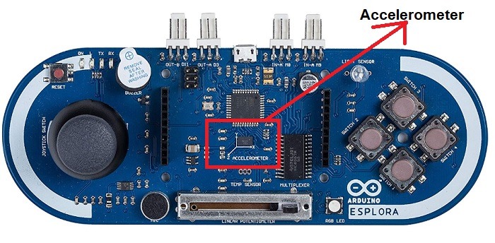
In this tutorial we will learn how to use the MPU6050 Accelerometer and Gyroscope sensor with the Arduino. I will explain how the MPU6050 works and Accelerometer Using Arduino 101: Learn how to read Accelerometer Sensor on Arduino 101 and show tilt status on LED. Arduino 101 is good for IOT starters. Having the Intel® Curie™ Module, designed to integrate the core's low power-consumption and high performance with the Arduino's …
How to use the MPU-6050 accelerometer and gyroscope module with the Arduino board. The MPU-6050 IMU is a 3-axis accelerometer and 3-axis gyroscope sensor. In this article, we will use an Arduino to get raw sensor data from an accelerometer and convert it into an acceleration value in g's. Watch the video for this tutorial here: In this article, we are going to interface the GY-521 accelerometer with Arduino. The GY-521 has an InvenSense MPU6050 chip which contains a 3-axis accelerometer and a 3-axis gyro meter. This makes it a 6 DOF IMU (6 degrees of freedom inertial measurement unit). The chip also includes a 16-bit analog to digital converter on each
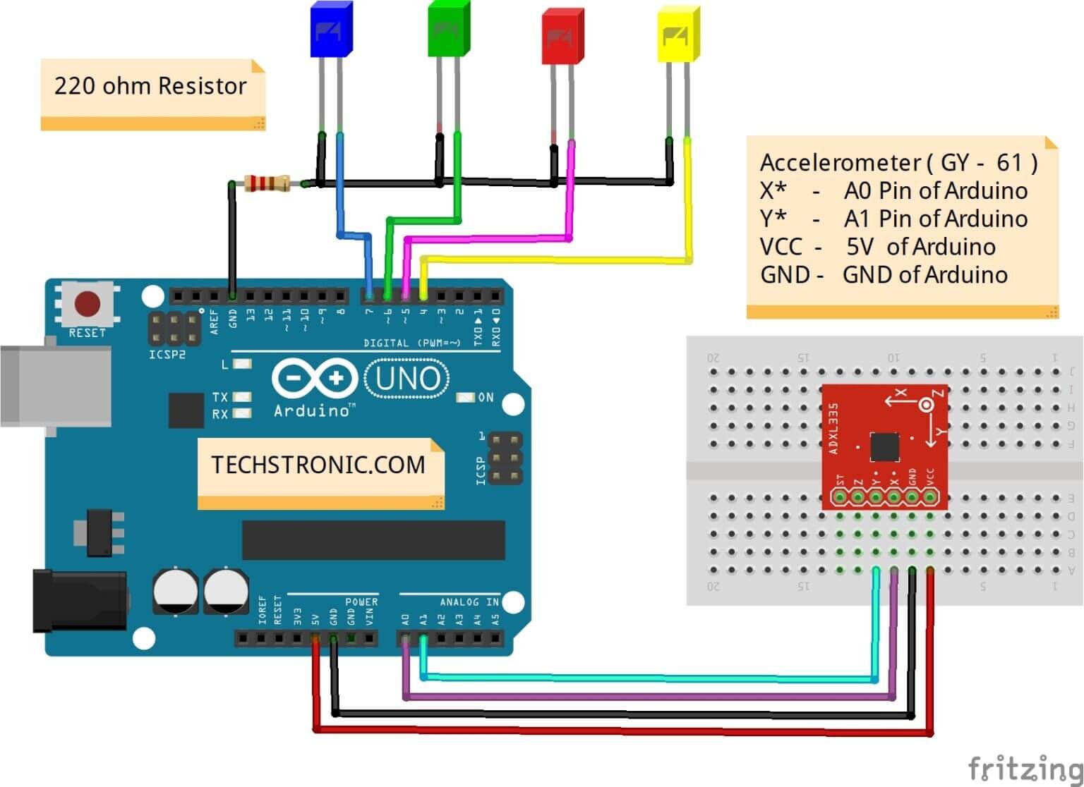
Accelerometer to Arduino Circuit Diagram
The accelerometer uses very little current, so it can be plugged into your board and run directly off of the output from the digital output pins. To do this, you'll use three of the analog input pins as digital I/O pins, for power and ground to the accelerometer, and for the self-test pin.